
Written by Applications Engineer, Craig Crossley
3D printed mold tools function differently than traditional steel or aluminum tools. They belong in a different stage of product development (i.e. when you need prototypes for functional testing), and also are designed differently. In fact, we put out a whole blog post on the difference between them, that you can check out here.
Just as the tools themselves are different, so is the molding process. Instead of the traditional Scientific Molding process that is generally accepted as the gold standard of molding, Fortify has developed processing parameters that work effectively with 3D printed tools.
Fortify’s molding process is a hybrid extrusion and molding process that fills cavities slowly at low pressures. For instance, we steer away from the normal short shot study and instead use a 85%-95% fill as our transfer part. Additionally, we forgo the gate freeze study, in-mold rheology curve and cooling time optimization to maximize the amount of usable prototypes that can be manufactured from our molds. The goal is to keep the cavity pressure as low and consistent as possible.
While this process eliminates many molding defects, some still occur using this process. Below is a list of the common injection molding defects seen with Fortify’s molding process – and how to troubleshoot them.
1. FLASH
Flash is a very common mold defect that occurs at the parting line or at insert mating locations. The first step is to identify the cause of the flash.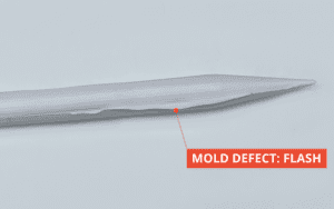
2. VOIDS / AIR TRAPS
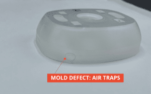 Voids and Air traps are often the sign of a venting issue or mold temperature issue in traditional metal tooling. Oftentimes in our process there is a very simple solution. If the voids or air traps are presenting themselves near an insert or ejector pin hole the fix would be increasing the hold time. Because our process is slower and lower pressure than normal it often takes much longer to push air through the natural venting locations on our molds. A hold time of 10-20 seconds is perfectly acceptable when using Fortify tooling. If these voids are occurring at the parting line, additional venting may be required.
3. WELD / KNIT / MELD LINES
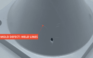
A common way to solve a very noticeable weld line would be to increase the mold temperature to help those flow lines better assimilate when they meet, however this will not be available when using Fortify tooling. The best way to eliminate this issue is to increase the pack pressure and time, but remember to not exceed 80% of your peak injection pressure for this pack pressure. If you are overpacking the part during this phase, resetting those values and instead increasing the injection velocity should allow for those flow fronts to merge while hotter and should eliminate the lines on the part. However, these defects are often a sign of a larger issue in the mold design where a large flow obstacle is present. Since these are prototype tools it is a lot better to solve this issue with a tool redesign, so that once your production run starts, you won’t have this defect.
Setting your processing strategy is just as important as designing the mold tools themselves for successful mold runs. The above strategies will help eliminate these part defects while using 3D printed tooling. Part 2 of this process troubleshooting series will cover how to get rid of sink, short shots and other common defects that you will face. Please stay tuned for more updates to this series, but for now you can learn more about optimal design tips for 3D printed mold tools, with our mold design video series.